Mission and Need
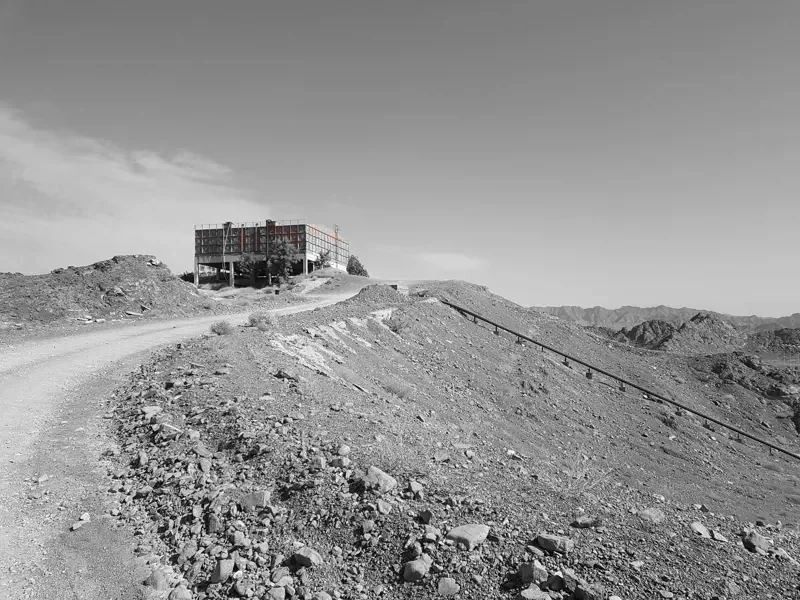
The water supply for a campus housing 5,000 people depended on a reservoir tank on a hill, filled by five well pumps at two sites, one inside the campus and four sharing a single underground pipe from up to 5 km away. Each pump ran on its own electrical panel and timer, so staff had to drive out to the wells, the tank could overflow, and a pump could run dry without anyone knowing.
The client wanted to see and control every pump from its control room, fill the tank automatically without overflowing, run the pumps in sequence, and detect leaks and dry running.
Our Role
SciFlair was the design authority, working with a local partner company. With no written specification, we and our partner elicited the stakeholder requirements through a site survey and discussions with the client's engineers, and set them out as the agreed scope. SciFlair designed and built the controllers, software and web application; our partner installed the system and provided two years of support. A single project manager was the point of contact, with acceptance signed off by the client's project manager.
What We Built
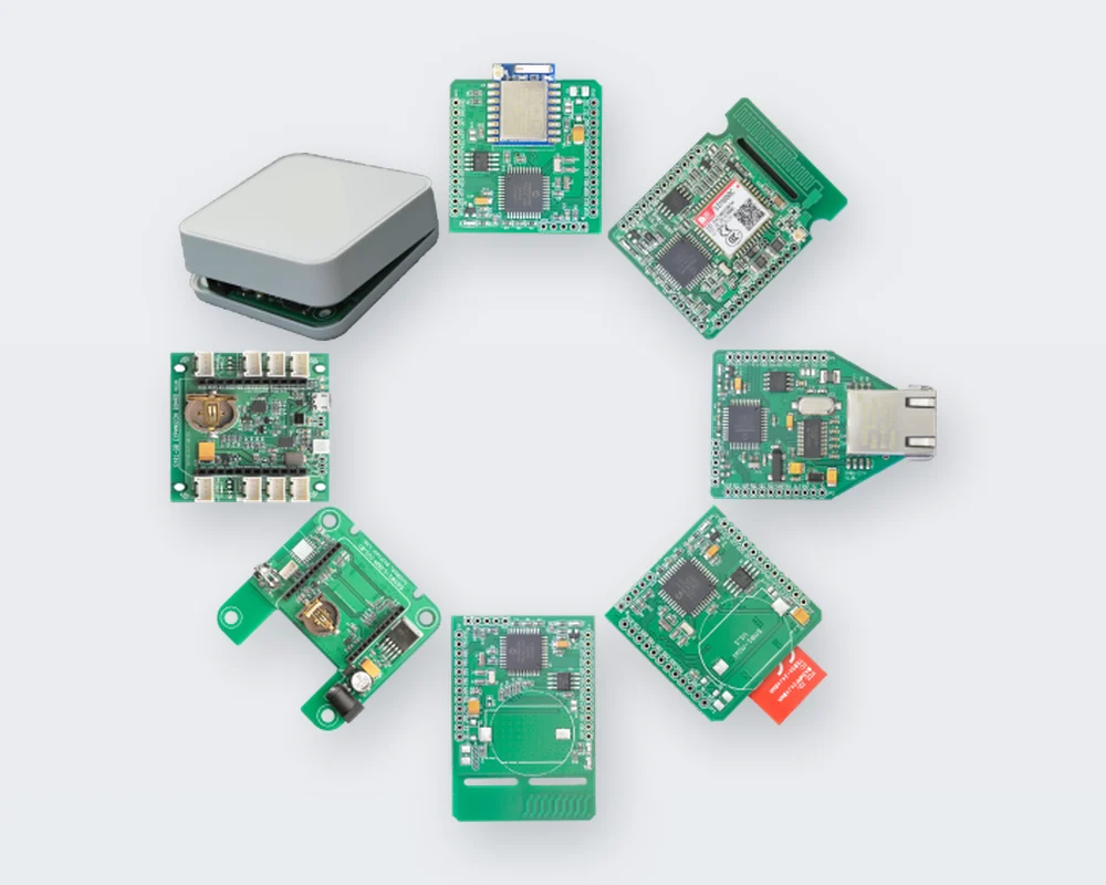
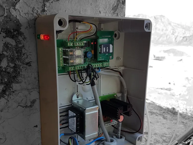
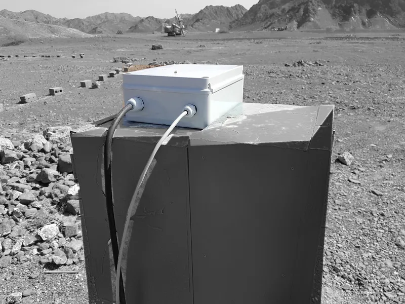
- Six GSM-connected controllers, one at the reservoir and one at each well, each built on our Axino SM01-GSM communication module with an RS485 expansion board and high-power relays to switch the pump, in sealed enclosures
- A level rod in the 3 m reservoir with six sensors at 0.5 m spacing, and green, yellow and red indicator lights on the tank controller
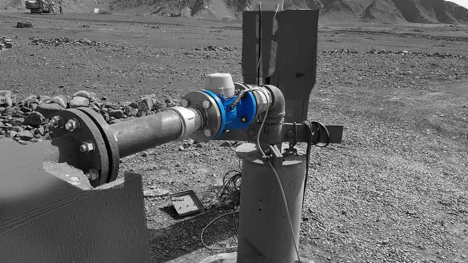
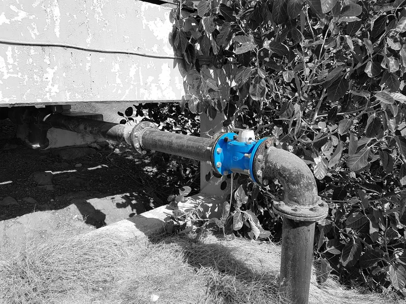
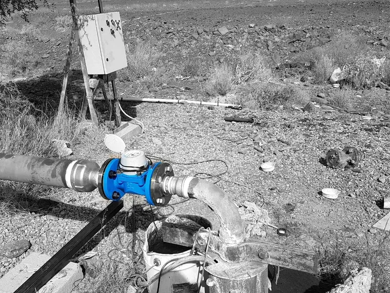
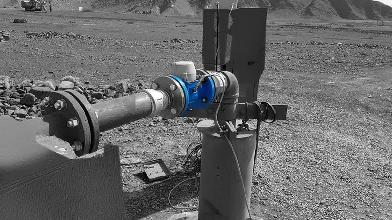
- Flow meters at each well and at the reservoir inlet, so the system can halt a pump that is running dry and spot leaks between source and delivery
- Control logic in each controller to fill the tank automatically, stop before overflow, run the pumps in sequence and give each motor rest time
- A manual, off and automatic switch at every pump panel, so operators can always override the system
- A web application on a map showing the tank level and each pump as running, stopped or halted with no flow, with on-screen buttons to control the pumps from the control room
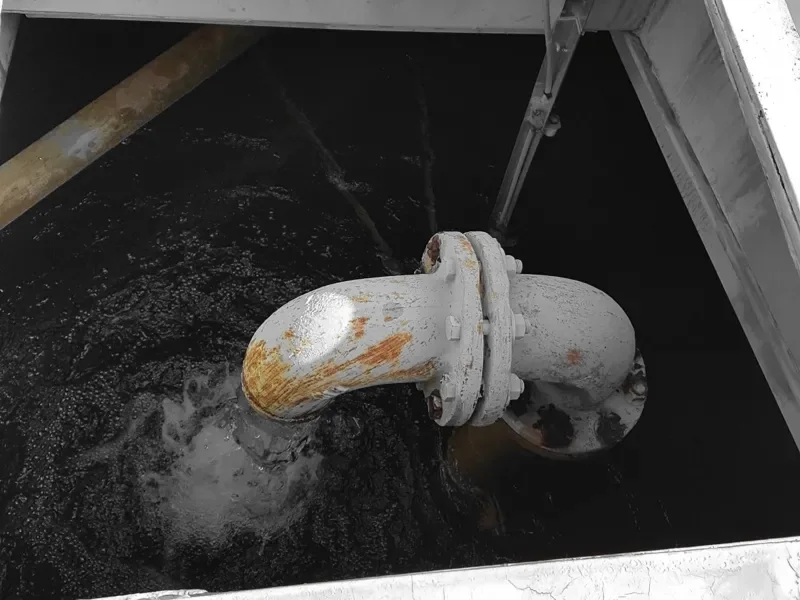
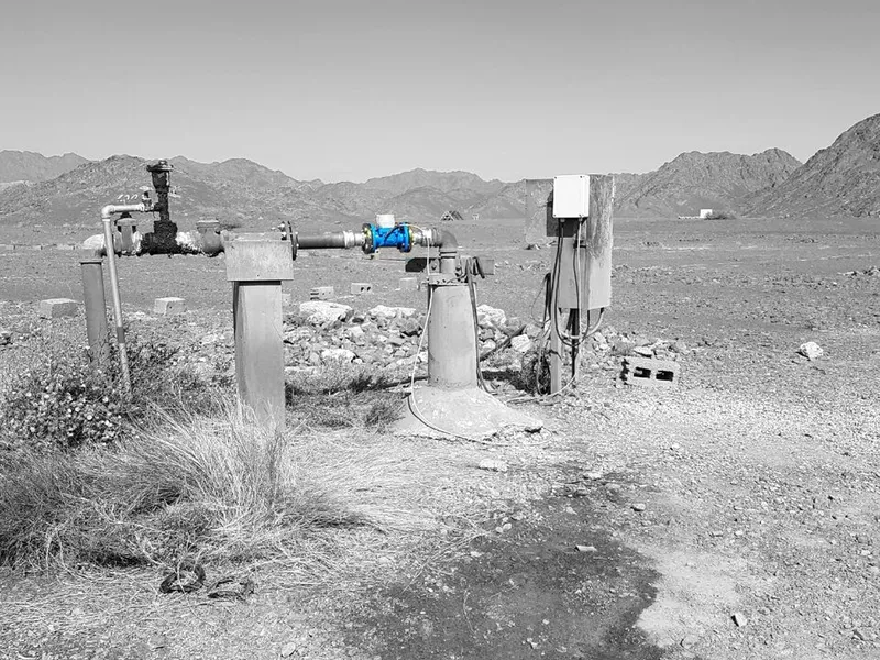
Five well pumps at two sites, the largest 25 HP, feeding one reservoir through an underground pipeline of up to 200 mm diameter.
How It Was Delivered
Stakeholder requirements
With no written specification, requirements were captured with our local partner through a site survey and discussions with the client's engineering team, then baselined as the project scope.
Stage plan
A 12-week plan from order to handover, with scope changes documented and justified through change control.
Verification
Each controller and its sensors were tested on site as they were deployed, against block diagrams produced for the tank and each pump.
Decision gate: primary acceptance
A first stage installed two controllers, tested and signed off by the client before the remaining wells were connected.
Validation and transition
All six controllers installed, a signed site acceptance test in operational use, and handover with system documentation and an operator guide to the web application.
Support
Two years of on-site support and maintenance by our local partner after handover, backed by SciFlair engineering.
Gallery

What came next: the SciFlair Water Control System
The design became our Water Control System product: an Axino module on a purpose-built expansion board, float-switch level sensors daisy-chained over RS485, and a choice of GSM, WiFi, Ethernet, LoRa, Mesh or SigFox connectivity. It prevents overflows, dry running and pump overheating, reports pipe bursts and unusual consumption, and integrates with other systems through webhooks and a REST API.